NF EV Battery Thermal Management Solution
Product Description

Battery thermal management system keep electric vehicle battery pack temperatures within the right range to maintain their longer driving range and extend battery life. We also call it BTMS Battery or Battery Chiller or Battery Pack Cooling System.
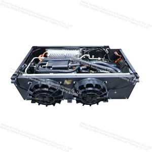
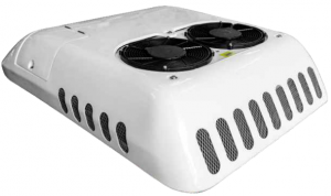
We specializes in developing thermal management systems for electric bus batteries, electric truck batteries, electric boat batteries and electric heavy equipment batteries. With a cooling/heating capacity of 3KW-10KW, they keep the temperature of the power battery pack in the optimal range by means of coolant cooling and PTC heating. This allows electric vehicles to achieve longer range and service life.
The optimal operating temperature of the battery is 20° to 45°. If this temperature is exceeded, the driving range and the life of the battery will drop dramatically. What’s more, it may also affect the surrounding equipment and cause the consequences of combustion and explosion. That’s why electric vehicles especially need a battery thermal management system, which we also call a BTMS or battery cooler or battery pack cooling system.
If the battery is below this temperature, its electrochemical reaction activity will become poor and the performance of the battery will be greatly reduced. It may even cut off the power directly. Our product can heat it, so we call it battery heating or battery heater.
Product Parameter
|
NO. |
Project |
Parameter Specifications |
|
1 |
Model |
EHP6.0-1 |
|
2 |
Refrigeration capacity |
7kW |
|
3 |
Heating capacity |
8kW |
|
4 |
Rated voltage |
600V DC |
|
5 |
Low voltage power supply |
18-32V DC |
|
6 |
Overvoltage protection/recovery voltage |
750/720V DC |
|
7 |
Undervoltage protection/recovery |
400/430V DC |
|
8 |
Refrigerant carrier |
50%/50%Ethylene Glycol/Water Solution |
|
9 |
Refrigerant |
R134a |
|
10 |
Compressor displacement |
34cc |
|
11 |
working temperature |
-40℃~50℃ |
|
12 |
Unit protection level |
IP67 |
|
13 |
Outer diameter of water inlet pipe |
Φ20mm |
|
14 |
Outer diameter of water outlet pipe |
Φ20mm |
|
15 |
Total weight |
<55kg |
|
16 |
Overall dimensions |
See drawings |
|
17 |
Installation method |
M10 bolt installation |
|
18 |
Installation dimensions |
See drawings |
|
19 |
Communication method |
CAN2.0 |
Working Principle
The schematic diagram of our EHP battery thermal management system is shown in Figure 2-1. The solid red line in the figure represents the refrigeration cycle, and the dashed blue line represents the coolant cycle. This unit has three modes, including cooling mode, heating mode, and self-circulation mode. The unit switches between these three modes based on the parameters feedback from the battery pack BMS.

Working Principle

Application

Company Profile


Certificate

Shipment

Customer Feedback